Subtotal: 2,500 د.ع
Smart Phone Controlled Digital Code Lock Using Arduino Leave a comment
There are many types of security systems used all over the world and Digital Code Lock is one of them. Here we are going to build a Smart Phone Controlled Digital Lock using TFT LCD and Arduino Mega. This lock can be controlled wirelessly via Bluetooth, using your Android phone, within the range of normal Bluetooth that is 10 meters. User needs to enter the Predefined password from his Android Phone, if password is correct TFT LCD shows the “CORRECT PASSWORD” message and if password is wrong then LCD shows the “WRONG PASSWORD” message.
By using this Lock, you can open the door lock, while walking, even before reaching to it. This will save your time and you don’t need to carry the keys and lock can be opened easily with your Phone.
Circuit Diagram and Explanation:

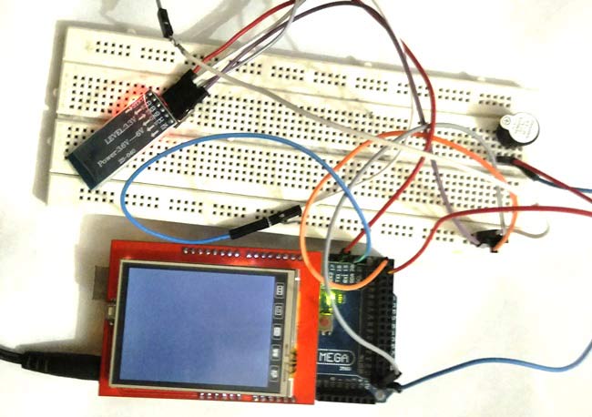
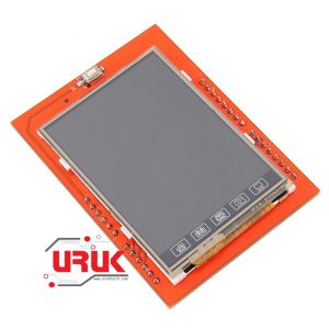
Circuit of this Smart Phone Controlled Digital Lock is simple; we only need to connect Bluetooth Module HC05 and TFT LCD Shield to the Arduino. TFT LCD shield can be easily mounted on Arduino, we just need match the alignment of pins and ensure that GND and Vcc pins of Arduino should be mounted on GND and Vcc pins of LCD. You also need to install the Library for TFT Touch Screen LCD, learn more about Interfacing TFT LCD with Arduino here.
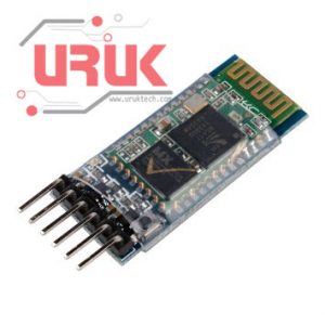
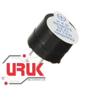
HC05 is powered by Arduino Vcc and GND Pins, TX of HC05 is connected to RX1 of Arduino and RX of HC05 is connected to TX1 of Arduino. One pin of buzzer is connected to GND of Arduino and other to pin 22 of Arduino.
Configuring Bluetooth Terminal App for Arduino:
To operate this Digital lock through our Android Smart Phone, first we need to install an Android Mobile App named Bluetooth Terminal. Bluetooth Terminal App is compatible with Arduino. This App can be downloaded from the Google Play Store, and can be easily configured by following below Steps:
- First download it from Google Play Store and install it in your Android mobile phone.
- Power up your ‘Bluetooth controlled Digital Lock system circuit’.
- Open the app and go to option ‘connect securely’.
- You will find HC05 device to pair.
- Give 1234 passkey to connect with your Android Phone, like we use to connect other Bluetooth Devices.
Working Description:
In this Arduino Based Security System, we have used three major components which are Bluetooth Module HC05, Arduino Mega Board and 2.4 inch TFT LCD Shield.
Here four digit Password is entered by user through Android Smart Phone using Bluetooth Terminal App and sent to the Arduino via Bluetooth. Arduino receives the data, sent by Android Phone, using Bluetooth Module HC05 and display it on SPFD5408 TFT LCD. Arduino compares the user entered Password with the Predefined password (1234), and displays the message accordingly. It displays the message “WRONG PASSWORD” if password don’t match and display the message “CORRECT PASSWORD” if password matches. A buzzer is also used for alarm indication, which beeps when password entered is wrong. Also Check the Video, shown at the end, to understand its operation.

We can also change the password to our choice by changing the Arduino Code, it has been explained in ‘Programming’ section below.
Programming Description:
To program this Bluetooth Controlled Digital Lock, we have used some libraries for displaying data on TFT LCD.
#include <SPFD5408_Adafruit_GFX.h> // Core graphics library
#include <SPFD5408_Adafruit_TFTLCD.h> // Hardware-specific library
#include <SPFD5408_TouchScreen.h>
Initialization of LCD input-output, and serial communication for Bluetooth module are performed invoid setup() loop. Pin number 22 of Arduino is interfaced to the buzzer and the other pin of buzzer is interfaced to ground of Arduino Mega. The Bluetooth module is interfaced with Serial1 port of Arduino Mega and powered by 5V supply of Arduino Mega.
fillScreen() function is used for clearing the LCD.
void setup() {
// put your setup code here, to run once:
Serial.begin(9600);
Serial1.begin(9600);
tft.reset();
tft.begin(0x9341);
tft.setRotation(0);
tft.fillScreen(WHITE);
tft.setCursor (40, 50);
tft.setTextSize (2);
tft.setTextColor(BLACK);
tft.println(“E N T E R* P A S S W O R D “);
delay(5000);
tft.fillScreen(WHITE);
pinMode(22,OUTPUT);}
In void loop() function, setTextSize(4) sets the size of text and setTextColor(colorName) sets the color of text. The arr[] is the array in which we have stored the predefined four digit password and theInput[] is the array in which we have stored the password entered by user from Android Phone. If password entered is same as the password stored, then the LCD will display “CORRECT PASSWORD” message and If it is not the same i.e. 1234, then the LCD will display “WRONG PASSWORD” message and the pin connected to buzzer becomes high and the buzzer beeps.
void loop() {
tft.setTextSize (4);
tft.setTextColor(CYAN); // put your main code here, to run repeatedly:
if (Serial1.available() > 0) {
flag = 1;
char c = Serial1.read();
if (flag == 1) {
input[i] = c;
…. …..
….. ……
We can further, alter the arr[] array to change the password of our choice instead of ‘1234’. We can also change the no. of characters in the password by changing the length of arr[] and input[] arrays.
char arr[4] = {‘1’, ‘2’, ‘3’, ‘4’};
char input[4];
According to the changed length of password we need to change the if condition in void loop()function.
if (arr[0] == input[0] && arr[1] == input[1] && arr[2] == input[2] && arr[3] == input[3])
Further we can interface a Electronic Door Lock (easily available online) in this project. It have an Electro magnet which keeps the Door locked when there is no current passed through the Lock (open circuit), and when some current passed through it, the lock gets unlocked and door can be opened. We just need to alter the Code accordingly, and we are ready to Open door Lock with our Phone.
Arduino Code
#include <SPFD5408_Adafruit_GFX.h> // Core graphics library
#include <SPFD5408_Adafruit_TFTLCD.h> // Hardware-specific library
#include <SPFD5408_TouchScreen.h>
// *** SPFD5408 change — End
#if defined(__SAM3X8E__)
#undef __FlashStringHelper::F(string_literal)
#define F(string_literal) string_literal
#endif
#define YP A1 // must be an analog pin, use “An” notation!
#define XM A2 // must be an analog pin, use “An” notation!
#define YM 7 // can be a digital pin
#define XP 6 // can be a digital pin
// Original values
//#define TS_MINX 150
//#define TS_MINY 120
//#define TS_MAXX 920
//#define TS_MAXY 940
// Calibrate values
#define TS_MINX 125
#define TS_MINY 85
#define TS_MAXX 965
#define TS_MAXY 905
// For better pressure precision, we need to know the resistance
// between X+ and X- Use any multimeter to read it
// For the one we’re using, its 300 ohms across the X plate
TouchScreen ts = TouchScreen(XP, YP, XM, YM, 300);
#define LCD_CS A3
#define LCD_CD A2
#define LCD_WR A1
#define LCD_RD A0
// optional
#define LCD_RESET A4
// Assign human-readable names to some common 16-bit color values:
#define BLACK 0x0000
#define BLUE 0x001F
#define RED 0xF800
#define GREEN 0x07E0
#define CYAN 0x07FF
#define MAGENTA 0xF81F
#define YELLOW 0xFFE0
#define WHITE 0xFFFF
char arr[4] = {‘1’, ‘2’, ‘3’, ‘4’};
char input[4];
char messageflagarr[4]; char result = ‘0’, flag = 0, passwordflag = 0;
int x = 40, i = 0;
Adafruit_TFTLCD tft(LCD_CS, LCD_CD, LCD_WR, LCD_RD, LCD_RESET);
void setup() {
// put your setup code here, to run once:
Serial.begin(9600);
Serial1.begin(9600);
tft.reset();
tft.begin(0x9341);
tft.setRotation(0);
tft.fillScreen(WHITE);
tft.setCursor (40, 50);
tft.setTextSize (2);
tft.setTextColor(BLACK);
tft.println(“E N T E R* P A S S W O R D “);
delay(5000);
tft.fillScreen(WHITE);
pinMode(22,OUTPUT);
}
void loop() {
tft.setTextSize (4);
tft.setTextColor(CYAN);
// put your main code here, to run repeatedly:
if (Serial1.available() > 0)
{
flag = 1;
char c = Serial1.read();
if (flag == 1)
{
input[i] = c;
i++;
tft.println(c);
delay(2000);
if (i == 4)
{
passwordflag = 1;
}
flag = 0;
}
if (passwordflag == 1)
{
if (arr[0] == input[0] && arr[1] == input[1] && arr[2] == input[2] && arr[3] == input[3])
{
tft.setCursor (40, 50);
tft.setTextSize (2);
tft.setTextColor(BLACK);
tft.println(“CORRECT PASSWORD”);
delay(6000);
tft.fillScreen(WHITE);
i=0;
}
else
{
tft.setCursor (40, 50);
tft.setTextSize (2);
tft.setTextColor(BLACK);
tft.println(“WRONG PASSWORD”);
digitalWrite(22,HIGH);
delay(500);
digitalWrite(22,LOW);
delay(500);
digitalWrite(22,HIGH);
delay(500);
digitalWrite(22,LOW);
delay(500);
digitalWrite(22,HIGH);
delay(500);
digitalWrite(22,LOW);
delay(500);
digitalWrite(22,HIGH);
delay(500);
digitalWrite(22,LOW);
tft.fillScreen(WHITE);
digitalWrite(22,LOW);
i=0;
}
passwordflag=0;
}
}
}
The items used in this experiment
المواد المستخدمة في التجربة يمكنكم اضافتها الى سلة مشترياتكم مباشرة من هنا
-
-
Boards
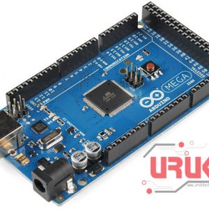
Arduino Mega 2560
اردوينو مييغا هي لوحة تطوري يحتوي على المتحكم Atmega2560 وهو متحكم تحتوي على 54 منفذ إدخال / إخراج رقمي (يمكن استخدام 15 منها كمخرجات تضمين عرض النبضة PWM )، و 16 مدخلًا تناظريًا، و 4 (منافذ تسلسلية Serial للأجهزة) ، ومذبذب كريستالي 16MHz، ووصلة (يو اس بى) ، ومقبس طاقة، وزر إعادة الضبط. ويحتوي على كل ما يلزم لدعم المتحكم الدقيق؛ ما عليك سوى توصيله بجهاز كمبيوتر باستخدام كيبل USB أو تشغيله على محول للتيار الثابت أو بطارية للبدء فى البرمجة.
SKU: 20








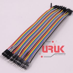 40 Male-Male Dupont Line