Operating 220V Device by using Arduino Leave a comment
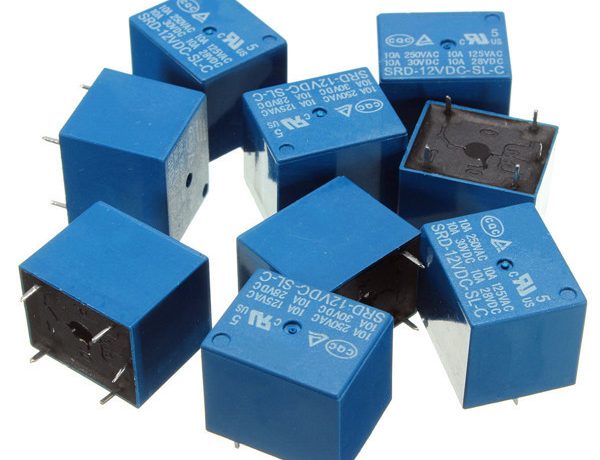
One of the most practical applications of the Arduino is controlling devices like box fans, light bulbs, and other home appliances. Since the Arduino operates at 5V, it cannot control these higher voltage (220V) devices directly. However, we can get around this problem by using a 5V relay to switch the 220V current and programming the Arduino to control the relay.
The best part about using an Arduino to control these devices is that we can program the Arduino to output a signal to the relay when a particular event occurs. For example, we can program the Arduino to turn the relay on if the temperature reading from a thermistor reaches 30° C or greater. We can program the Arduino to turn the relay off when the resistance from a photoresistor drops below 400 Ohms. Any sensor can be used to trigger the relay to turn on or off. The trigger doesn’t even need to be from a sensor, it can also be based on time or any other variable.
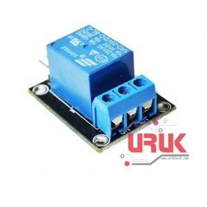
I’ll be using the 1-Channel 5V Relay to demonstrate here because it’s very popular among Arduino and Raspberry Pi users. Now let’s dive into how the 5V relay works and how to set it up on the Arduino.

The 5V relay I’ll be using here is called the 1-Channel 5V Relay. Inside the unit is a 220V switch that is connected to an electromagnet. When the relay receives a HIGH signal at its signal pin, the electromagnet becomes charged and moves the contacts of the 220V switch open or closed.
Normally Open vs. Normally Closed
This relay actually has two different types of electrical contacts inside – normally open (NO) and normally closed (NC). The one you use will depend on whether you want the 5V signal to turn the switch on or turn the switch off. The 220V supply current enters the relay at the common (C) terminal in both configurations. To use the normally open contacts, use the NO terminal. To use the normally closed contacts, use the NC terminal.
Normally Open
In the normally open configuration, the 220V electrical contacts are open until the relay receives the signal that closes the contacts and allows current to flow. So if we want the signal to turn on the current, we use the normally open terminal when wiring the outlet.
Normally Closed
In the normally closed configuration, the electrical contacts are closed until the relay receives the signal, which opens the contacts and interrupts the current. Thus, if we want the signal to turn off the 220V current, we use the normally closed terminal.
Temperature Dependent Switch for 220V Devices
Thermistors are useful components to use with 5V relays since you can use them to turn on or off appliances when they reach a certain temperature. For example, you could turn off a large motor if gets too hot, or turn on a heater if the temperature gets too cold.
WARNING – THIS PROJECT INVOLVES HIGH VOLTAGES THAT CAN CAUSE SERIOUS INJURY OR DEATH. PLEASE TAKE ALL NECESSARY PRECAUTIONS, AND TURN OFF ALL POWER TO A CIRCUIT BEFORE WORKING ON IT.
In this example, I will use an Arduino coupled with thermistor and a 5V relay to turn off a light bulb when the temperature around the thermistor reaches 150 °F. The set up is simple:

Connect the power wire of the light bulb cord to the NO (normally open) terminal of the relay, and connect the neutral power wire of the cord to the C (common) terminal of the relay.
The thermistor part of the circuit above is a voltage divider, so the value of the resistor should be the same order of magnitude as the value of the thermistor. For example, I used a 10K Ω thermistor, so the resistor should be 10K Ω as well. If you use a 100K Ω thermistor, use a 100K Ω resistor. If you use a 100K Ω thermistor, you’ll need to change line 7 in the code below to Temp = log(100000.0*((1024.0/RawADC-1)));. See our article on Making an Arduino Temperature Sensor for more setup information.
After everything is connected, upload this code to the Arduino:
Arduino Code
#include <math.h>
int pinOut = 10;
double Thermistor(int RawADC) {
double Temp;
Temp = log(10000.0*((1024.0/RawADC-1)));
Temp = 1 / (0.001129148 + (0.000234125 + (0.0000000876741 * Temp * Temp ))* Temp );
Temp = Temp – 273.15;
Temp = (Temp * 9.0)/ 5.0 + 32.0;
return Temp;
}
void setup() {
Serial.begin(9600);
pinMode(10, OUTPUT);
}
void loop() {
int val;
double temp;
val=analogRead(0);
temp=Thermistor(val);
Serial.print(“Temperature = “);
Serial.print(temp);
Serial.println(” F”);
if (temp >= 150){
digitalWrite(pinOut, LOW);
}
else {
digitalWrite(pinOut, HIGH);
}
delay(500);
}
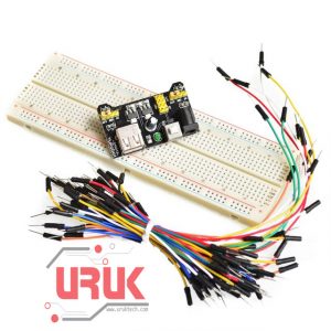
The items used in this experiment
المواد المستخدمة في التجربة يمكنكم اضافتها الى سلة مشترياتكم مباشرة من هنا
In this example, the relay stays activated and current flows through the light bulb until the temperature at the thermistor reaches 150 °F, at which point the relay shuts off and the current stops. Once the temperature drops below 150 °F, the relay will be activated, and it will switch the power back on. You can change the temperature that the relay turns on and off in line 27 (if (temp >= 150){).


