Subtotal: 2,000 د.ع
Arduino With Raindrop Module Leave a comment
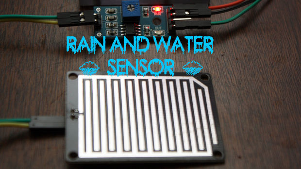
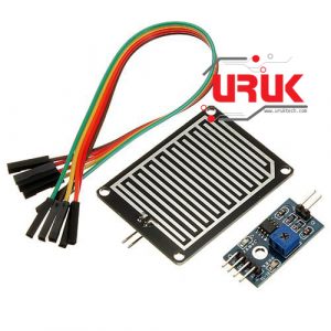
Quick and simple start guide for using and exploring the Rain Sensor module sometimes called a “Raindrops Sensor Module” with an Arduino.
Materials needed:
- Rain Sensor
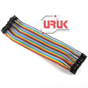
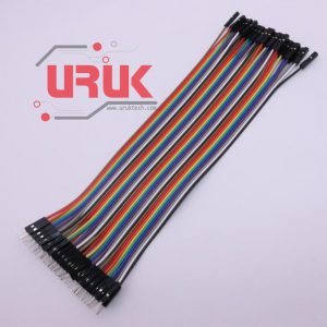
- 3x Male to Female jumper wires
- 2x Female to Female jumper wires
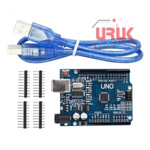
- An Arduino, any flavour
- Source of water
Step 1: Getting to know your Rain Sensor:
Usage:

Rain sensors are used in the detection of water beyond what a humidity sensor can detect.
How it works:
The rain sensor detects water that completes the circuits on its sensor boards’ printed leads. The sensor board acts as a variable resistor that will change from 100k ohms when wet to 2M ohms when dry. In short, the wetter the board the more current that will be conducted.
Pins:
A0………. Analog output
D0……… Digital output
GND….. Ground
VCC…… Positive voltage (input: 5v for analog 3.3v for Digital.)
Loop Pins:
+ ………. Sensor board hookup A
– ………. Sensor board hookup B
Dimensions:
2.17 in x 1.57 in x 0.31 in (5.5 cm x 4.0 cm x 0.8 cm)
Weight:
0.28 oz (8 g)
Step 2: Testing and Troubleshooting:

Testing:
To test the Rain Sensor and ensure that it is working correctly connect the VCC to a 5v power source and GND. Try placing a few droplets of water on the Rain sensor detection board and the D0-LED should light up.
Troubleshooting:
If the D0-LED does not light up check the following:
- Is the module hooked up properly?
- Sometimes salinity is an issue with these units, this one worked fine with filtered, bottled water, but in some instances you may have to add a bit of salt to increase the waters conduction.
- This might be a bit more tricky, but for some reason two different models by two different manufacturers have had defects in their soldering skills. Make sure all of the little SMD’s and connectors have been soldered on properly. IE – are solder joints actually soldered?
- If none of the previous makes the D0-LED light up, your sensor may be defective.
Step 3: Wiring to an Arduino:

To wire the Rain Sensor to the Arduino for analog, simply connect the following as shown:
Rain Sensor …………….. Arduino
VCC…………………………. 5v
GND………………………… GND
A0……………………………. Analog in 0
Rain Sensor ……………. Sensor Board
+……………………………… +
-………………………………. –
Step 4: Arduino Sketch Example:

The following code maps and reads the analog values given by the Rain Sensor (0-1024). The Rain Sensor will have the following reaction with this code:
- If the Sensor Board is completely soaked; “case 0″ will be activated and ” Flood ” will be sent to the serial monitor.
- If the Sensor Board has water droplets on it; “case 1″ will be activated and ” Rain Warning ” will be sent to the serial monitor.
- If the Sensor Board is dry; “case 2″ will be activated and ” Not Raining ” will be sent to the serial monitor.
* The output in “case 2”, “Not Raining” is just for this demonstration. When I used this code in production I omitted the output for this case and just had the alert for “Rain Warning” and “Flood”.
* To view the output, point a serial monitor such as Putty at your Arduino.
* This code is constantly updating in order to provide a real time feedback of the Rain Sensor.
Arduino Code
/* Flame Sensor analog example.
For use with a Rain Sensor with an analog out!
To test view the output, point a serial monitor such as Putty at your Arduino.
– If the Sensor Board is completely soaked; “case 0″ will be activated and ” Flood ” will be sent to the serial monitor.
– If the Sensor Board has water droplets on it; “case 1″ will be activated and ” Rain Warning ” will be sent to the serial monitor.
– If the Sensor Board is dry; “case 2″ will be activated and ” Not Raining ” will be sent to the serial monitor.
*/
// lowest and highest sensor readings:
const int sensorMin = 0; // sensor minimum
const int sensorMax = 1024; // sensor maximum
void setup() {
// initialize serial communication @ 9600 baud:
Serial.begin(9600);
}
void loop() {
// read the sensor on analog A0:
int sensorReading = analogRead(A0);
// map the sensor range (four options):
// ex: ‘long int map(long int, long int, long int, long int, long int)’
int range = map(sensorReading, sensorMin, sensorMax, 0, 3);
// range value:
switch (range) {
case 0: // Sensor getting wet
Serial.println(“Flood”);
break;
case 1: // Sensor getting wet
Serial.println(“Rain Warning”);
break;
case 2: // Sensor dry – To shut this up delete the ” Serial.println(“Not Raining”); ” below.
Serial.println(“Not Raining”);
break;
}
delay(1); // delay between reads
}
The items used in this experiment
المواد المستخدمة في التجربة يمكنكم اضافتها الى سلة مشترياتكم مباشرة من هنا
In this example, the relay stays activated and current flows through the light bulb until the temperature at the thermistor reaches 150 °F, at which point the relay shuts off and the current stops. Once the temperature drops below 150 °F, the relay will be activated, and it will switch the power back on. You can change the temperature that the relay turns on and off in line 27 (if (temp >= 150){).










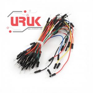 65 Flexible Wire Jumpers