Arduino MIDI Laser Harp Leave a comment
This is a basic introduction to make a framed laser harp with an Arduino. This laser harp is safe, cheap and temporary, and only intended to be a basis for a more complex design. It should only take a couple of hours to build.
Step 1: The Basic Principle

In a framed laser harp, each laser source is paired with a light detector a short distance away. The Arduino continuously monitors the light level at each light detector.
If the light level at a detector drops, we know that the laser beam has been blocked, and we send a MIDI “note on” message to the computer via the USB port (or by another means). If the light level returns, we send a MIDI “note off” message to the computer.
Step 2: Gathering Materials

As mentioned, this is intended to be as quick and cheap as possible:
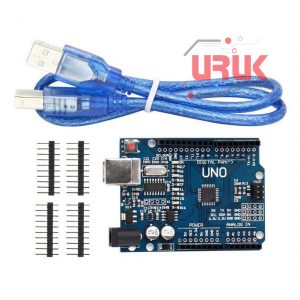
- 1 x Arduino (rev3) and USB cable
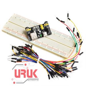
- A reasonably sized piece of breadboard (or 2)
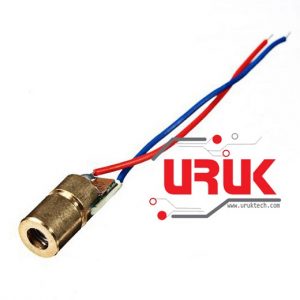
- 6 x Laser modules
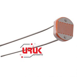
- 6 x visible light photodiodes
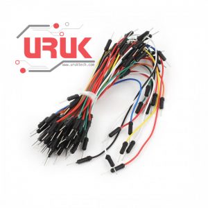
- Single core wire or jumper cables for making connections
- A selection of resistors (which you’ll use depends on your lasers and photodiodes – I’m using 6 x 100ohm and 6 x 100Kohm)
Step 3: Wiring the Laser Modules


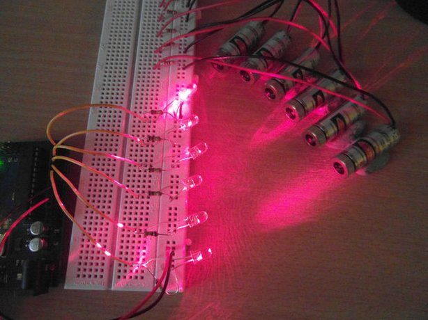
You’ll need to wire your laser modules in parallel, with a current limiting resistor for each module. Your resistor value should be matched to your diode, but 100 ohms should be sufficient. If you’re unsure. Stick each laser module down with a generous blob of blue-tack, aiming them roughly where you expect to have the light detector array. Alternatively, you could manufacture a frame that holds them in place.
Step 4: Wiring the Photodiodes


Each photodiode needs a 100K resistor, wired as in the image and schematic above. The photodiodes need to be reverse-biased when connected – put simply, the opposite way round to the way you’d wire an LED.
Step 5: Connect the power and turn it on

Now you’ll need to run a cable from the 5v and GND pin on the Arduino, and connect it to the 5v and ground rails on the breadboard. Plug in the Arduino briefly to check that everything switches on. If it doesn’t, check for bad connections and short-circuits.
If all is good, you can take a moment to align the lasers so each is pointing at it’s photodiode partner. It’s useful to have a piece of paper while you do this.

Step 6: The Arduino Sketch
Upload the sketch below to your Arduino. Open the serial window and check that you receive messages like “Note On message: note 64, velocity 100” when expected. If you have any stuck notes, or other strange behaviour, check your lasers are aligned and that you’re getting analogRead() values that go from 1024 to around 40 when the beam is broken. You can change the threshold variable from 512 to something else if necessary.
Arduino Code
const int notes=6; // set up number of notes
boolean notePlaying[notes]; //note states array: keeps track of whether a MIDI note is “on” or “off”
int scale[notes]={0,2,4,5,7,9}; //major scale
int beginNote=0x3C; //starting note value (default middle C)
int threshold=512; //value which analogRead() must cross for a midi note to be triggered
boolean midiMode=false; //set this to “true” before uploading MIDI f
void setup(){
if(midiMode){
Serial.begin(115200); //midi USB baud rate = 115200
}else{
Serial.begin(9600); //for testing values
}
}
void loop() {
for(int i=0;i<notes;i++){
if((analogRead(i)<threshold)&&(notePlaying[i]==false)){ //note on & CC messages
int note=beginNote+scale[i];
midiMessage(0x90, 1, note, 100);
notePlaying[i]=true;
}
if((analogRead(i)>threshold)&&(notePlaying[i]==true)){ //note off messages
int note=beginNote+scale[i];
midiMessage(0x80, 1, note, 0x00);
notePlaying[i]=false;
}
}
}
void midiMessage(int commandByte, int channelByte, int data1Byte, int data2Byte) {
if(midiMode){
Serial.write(commandByte);
Serial.write(channelByte);
Serial.write(data1Byte);
Serial.write(data2Byte);
}else{
if(commandByte==0x90){
Serial.print(“Note On message: note “);
}else if(commandByte==0x80){
Serial.print(“Note Off message: note “);
}
Serial.print(data1Byte);
Serial.print(“, velocity “);
Serial.println(data2Byte);
}
}
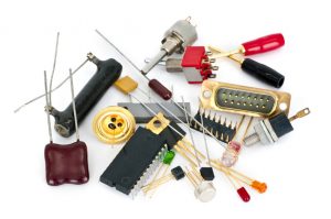
The items used in this experiment
المواد المستخدمة في التجربة يمكنكم اضافتها الى سلة مشترياتكم مباشرة من هنا
Experiment Name
Step 7: Finished!
Reset the Arduino and it should be automatically recognised as a MIDI device. Now you can open your audio software and test it out. It should behave something like the video.
The scale played is a C major. You can change this by editing the array “scale”, commented
//major scale
in the sketch. Remember you’ll have to flash the default Arduino firmware to upload any changes.
I hope this works out for you! Perhaps you feel like putting this into a frame, or adding more lasers & controls, or building it the size of a corridor, or all of the above. Good luck!


