4×4 keypad and Arduino Leave a comment
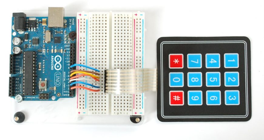
Keypad used usually in most of projects to enable customer to deal with project such as (Real Time Clock (RTC) to adjust day,time ,access control,…..etc) but if you use it with keypad library of Arduino it’s so easy and not good so here we will learn how to use it with Arduino without using keypad library.
Step 1: Components
all components we need are :
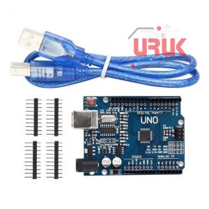
1- Arduino Uno Or Mega
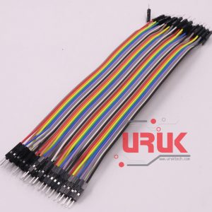
2- 8 x Arduino Connection Wires (Male-Male)
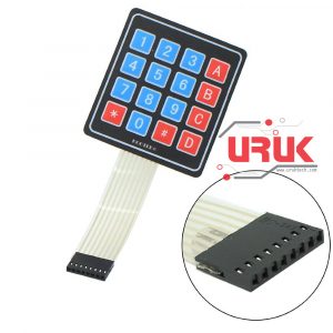
3- 4×4 matrix keypad.
Step 2: Calculation of Index Of Any Element In 4×4 Matrix

if we look to the above picture we obtain that index of any element is equal to
index=Number of Row x4 +Number Of Column.
Step 3: Connection


First Here Is The Pin configuration of keypad ….
R …. indicates the Row
C …. indicates the Column
Second Connect Keypad To Arduino As Following
Keypad Pin R1 –> Arduino Pin 2
Keypad Pin R2 –> Arduino Pin 3
Keypad Pin R3 –> Arduino Pin 4
Keypad Pin R4 –> Arduino Pin 5
Keypad Pin C1 –> Arduino Pin 6
Keypad Pin C2 –> Arduino Pin 7
Keypad Pin C3 –> Arduino Pin 8
Keypad Pin C4 –> Arduino Pin 9
Step 4: Upload The Code And Explaining
To illustrate the code i will explain it in few lines:
the following instructions are repeatedly executed every 50ms first it check if no button is pressed if that’s true the no press flag will be set to ONE and counters h and v will be reset to ZERO then all outputs will be LOW then check all inputs if any one of them is LOW( h became the number of column) a for loop changes first output to HIGH if the input Which Was LOW is change to HIGH That’s Mean that’s is the correct row of ( v became the number of row) then make all output as low to disable an pressed until you released the pressed button Reset The no press flag to ZERO and calculate the index and return it while you hold any button the no press flag is ZERO and the function return 50 and switch case used to output on serial monitor according to the return form keypad function.
Arduino Code (Without Using the Keypad Library)
byte h=0,v=0; //variables used in for loops
const unsigned long period=50; //little period used to prevent error
unsigned long kdelay=0; // variable used in non-blocking delay
const byte rows=4; //number of rows of keypad
const byte columns=4; //number of columnss of keypad
const byte Output[rows]={2,3,4,5}; //array of pins used as output for rows of keypad
const byte Input[columns]={6,7,8,9}; //array of pins used as input for columnss of keypad
byte keypad() // function used to detect which button is used
{
static bool no_press_flag=0; //static flag used to ensure no button is pressed
for(byte x=0;x<columns;x++) // for loop used to read all inputs of keypad to ensure no button is pressed
{
if (digitalRead(Input[x])==HIGH); //read evry input if high continue else break;
else
break;
if(x==(columns-1)) //if no button is pressed
{
no_press_flag=1;
h=0;
v=0;
}
}
if(no_press_flag==1) //if no button is pressed
{
for(byte r=0;r<rows;r++) //for loop used to make all output as low
digitalWrite(Output[r],LOW);
for(h=0;h<columns;h++) // for loop to check if one of inputs is low
{
if(digitalRead(Input[h])==HIGH) //if specific input is remain high (no press on it) continue
continue;
else //if one of inputs is low
{
for (v=0;v<rows;v++) //for loop used to specify the number of row
{
digitalWrite(Output[v],HIGH); //make specified output as HIGH
if(digitalRead(Input[h])==HIGH) //if the input that selected from first sor loop is change to high
{
no_press_flag=0; //reset the no press flag;
for(byte w=0;w<rows;w++) // make all outputs as low
digitalWrite(Output[w],LOW);
return v*4+h; //return number of button
}}}}}
return 50;
}
void setup()
{
for(byte i=0;i<rows;i++) //for loop used to make pin mode of outputs as output
{
pinMode(Output[i],OUTPUT);
}
for(byte s=0;s<columns;s++) //for loop used to makk pin mode of inputs as inputpullup
{
pinMode(Input[s],INPUT_PULLUP);
}
Serial.begin(9600); //to use serial monitor we set the buad rate
}
void loop()
{
if(millis()-kdelay>period) //used to make non-blocking delay
{
kdelay=millis(); //capture time from millis function
switch (keypad()) //switch used to specify which button
{
case 0:
Serial.println(1);
break;
case 1:
Serial.println(2);
break;
case 2:
Serial.println(3);
break;
case 3:
Serial.println(“F1”);
break;
case 4:
Serial.println(4);
break;
case 5:
Serial.println(5);
break;
case 6:
Serial.println(6);
break;
case 7:
Serial.println(“F2”);
break;
case 8:
Serial.println(7);
break;
case 9:
Serial.println(8);
break;
case 10:
Serial.println(9);
break;
case 11:
Serial.println(“F3”);
break;
case 12:
Serial.println(“Mode”);
break;
case 13:
Serial.println(0);
break;
case 14:
Serial.println(“Cancel”);
break;
case 15:
Serial.println(“Enter”);
break;
default:
;
}}}


